1. Safety Instruction
1.1 General Safety Regulation
Do not attempt to operate until you have read thoroughly and understand completely all instructions, rules, etc. contained in this manual. Failure to comply can result in accidents involving fire, electric shock, or serious personal injury. Keep owners manual and review frequently for continuous safe operation.
1.2Important safety notes
Concerning symbols used on the extraction unit and referred to within this manual.
Danger
Refers to an immediately impending danger. If the danger is not avoided, it could result in death or severe (crippling) injury. Please consult the manual when this symbol is displayed.
Warning
Refers to a possibly dangerous situation. If not avoided, it could result in death or severe injury. Please consult the manual when this symbol is displayed.
Caution
Refers to a possibly harmful situation. If not avoided, damage could be caused to the product or something in its environment.
Important (Refer to manual)
Refers to handling tip and other particularly useful information. This does not signify a dangerous or harmful situation. Refer to manual when this symbol is displayed.
Electrical Safety
The system has been designed to meet the safety requirements of the Low Voltage Directive 2006/95/EC.
Warning
When working with the pump/motor housing open, Live 230/115 volt mains components are accessible. Ensure that the rules and regulations for work on live components are always observed.
Important
To reduce the risk of fire, electric shock or injury:
1.Always isolate the system from the mains power supply before removing the motor access panel.
2.Use only as described in this manual.
3.Connect the system to a properly grounded outlet.
Dangers to eyes, breathing and skin
Once used, the filters within the system may contain a mixture of particulates, some of which may be sub-micron size. When the used filters are moved, it may agitate some of this particulate, which could get into the breathing zone and eyes of the operative. Additionally, depending on the materials being lasered, the particulate may be an irritant to the skin.
This unit should not be used on processes with sparks of flammable materials or with explosive dusts and gases, without implementation of additional precautions.
Caution: Always wear a mask, safety shoes, goggles and gloves when change used filters.
Carbon selection
Please note that the media within the gas filter fitted in the system is capable of adsorbing a wide range of organic compounds. However, it is the responsibility of the user to ensure it is suitable for the particular application the extraction is being used on.
1.3 Safety Labels
The following listing detail labels are used on our fume extraction unit.
Goggles, Gloves & Mask Label

Location: Front of both filters.
Meaning: Goggles, Gloves and Masks should be worn while handling used filters.
Do Not Touch Label
Location: Under the blower air inlet.
Meaning: Do not touch the holes adjacent to the label.
Electrical Danger
Location: Internal access panel..
Meaning: Removal of panels with this label attached will allow access to potentially live components.
Warning Label
Location: Top left front door panel.
Meaning: Power should be isolated before the panel with this label attached is opened/ removed.
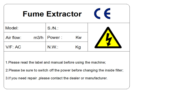
Location: Top right on the right side panel.
Meaning: This label contains a variety of information about the extraction unit, including.
A. Machine model;
B. Machine factory number;
C. Working voltage and frequency;
D. Rated power;
E. Machine weight;
F. Company name, address and contact number;
G. Related Marks / Logos
Please note: If the equipment is used in a manner not specified by the manufacturer, the protection provided by the equipment may be affected or equipment components may be damaged beyond repair.
Fire Risk Warning:
In the very rare event that a burning ember or spark is drawn into the fume extraction unit, it may be possible that the filters will ignite.
Whilst any resultant fire would typically be retained within the fume extraction unit, the damage to the extractor would be significant.
It is therefore essential to minimise this risk by undertaking an appropriate assessment to determine:
a). Whether additional fire protection equipment equipment be installed..
b). Appropriate maintenance procedures to prevent the risk of build-up of debris which could potentially combust.
2. Equipment related parameters
2.1 Equipment functions
(1) .Working principle:
The high-performance brushless fan in the purifier generates wind pressure, sucks smoke and exhaust gas into the filter, and purifies it by multi-stage filter elements such as primary efficiency, intermediate efficiency, high efficiency, and gas filter for indoor discharge.
(2). Features and advantages:
A. The machine is small size, low operating noise and easy to move;
B. Low power consumption and high efficiency brushless fan, stable operation and long service life;
C. Air volume adjustment can be realized, and the LCD display screen can show the machine's air volume in real time;
D. The control system comes with a filter clogging alarm function, prompting customers to replace the filter in time;
E. Configure the remote control to operate the machine from a distance;
F. Three-stage filters to ensure complete purification of soot and harmful substances;
G. The filter elements can be replaced separately, which reduces the use cost of the filter element and makes it easier to maintain and replace the filter elements;
H. High filtration efficiency, reaching 99.7%@0.3 microns (note: our self-test);
2.2 Machine Specification
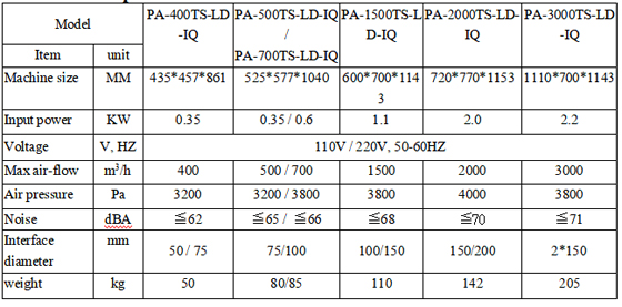
2.3 Filter elements Data
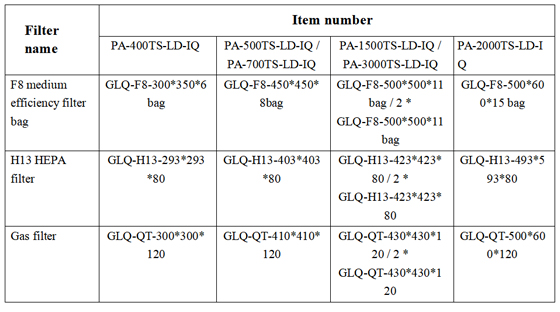
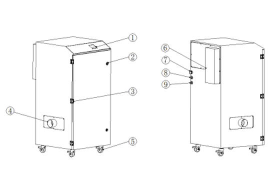
2.4 Appearance parts drawing:
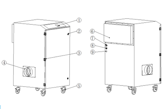
2.4.1 PA-400TS-LD-IQ / PA-500TS-LD-IQ / PA-700TS-LD-IQ / PA-1500TS-LD-IQ appearance parts drawing:
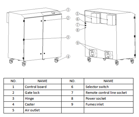
2.4.2 PA-2000TS-LD-IQ appearance parts drawing:
2.4.3 PA-3000TS-LD-IQ appearance parts drawing:
3. Installation
3.1 Installation instructions
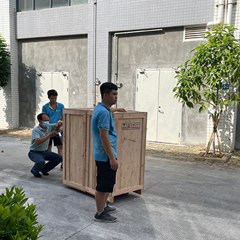
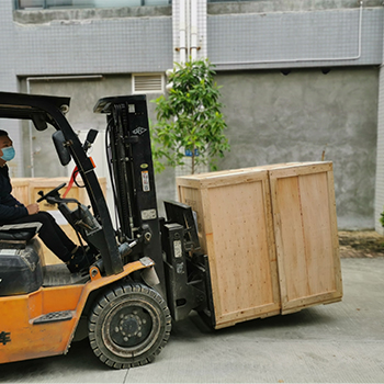
Before installation, the internal and external shipping packaging should be removed and the machine inspected for damage. Remove all the packaging before connecting the device to a power source.
Please read all instructions in this manual before using this fume extractor.
(1). Move the device to the location where you want to install it, and then remove the packaging. The device should be installed in a well-ventilated area.
(2). Open the top cover, check and ensure that the internal filter is smoothly placed in the limit interval, and check the top cover and the filter are sealed.
Attention:
A. Due to the weight of the fume extractor, proper handling methods and proper safety precautions should be followed.
B. Make sure that there is a space of 500 mm on the side of the air outlet of the fume extractor to ensure that there is sufficient air flow out.
(3). Lock the brake of the machine's casters to prevent the machine from sliding. (Some models do not have casters installed as standard.)

Attention:
A. Do not block or cover the air inlet on the device, as this will severely restrict airflow and may cause damage to the device.
B. Under no circumstances should the exhaust vent be covered as this will restrict airflow and cause overheating
3.2 Installation
(1).  :
:
(2). Machine assembly sequence: first assemble the host, then assemble the interface, power and signal cables.
Note: Confirm the distance and the flatness of the ground before assembly.。
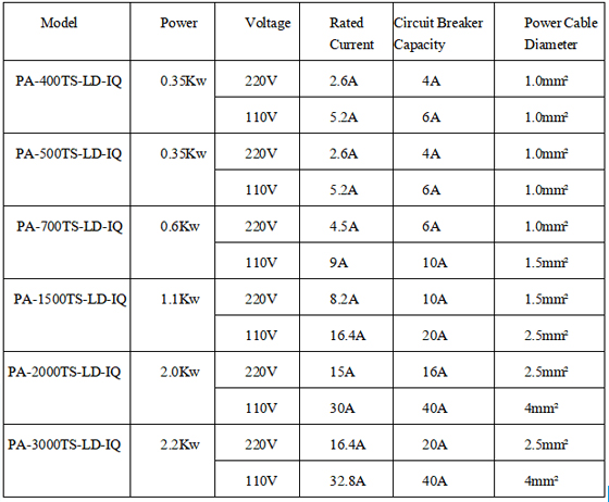
3.3 Power requirements
A. Insufficient power supply voltage may affect the power output function of the motor.
B. It is important to connect the unit to the correct voltage in the factory power source and use a separate power source.
C. Power requirements:
3.4 Check connection of power lines
Must check whether the power cord is connected to the correct connection point.
4. Operation
4.1 Control Panel

(1). Red "I" is the power button;
(2). Green "*" is the setting button;
(3). Green "-" is the button for reducing air volume;
(4). Green "+" is the button for increasing the air volume;
(5). The display shows: fan speed (RPM), air volume (m3 / h), gear position (1-10), filter element clogging alarm symbol (triangle).
4.2 Operating procedures
(1). Power connection: Before connecting the power supply, must confirm that the voltage and frequency meet the equipment's rated standards.
(2). Air pipe connection: The air pipe and equipment connection need to be of proper length and sealed to avoid the pipeline from collapsing and affecting the air flow.
(3). Machine start up and operation:
A. After connecting the power, turn on the power switch. The red indicator of the power switch will light up. If the machine doesn’t install remote start knob , the indicator light of the red "I" button on the control panel will light up and flash, and the machine is in standby state. If the remote start knob is installed on the machine, you need to rotate the knob to the "local" position, and the control panel The indicator light of the red "I" button will light up and blink, and the machine is in standby state;
B. Press the red "I" button on the control panel to start the machine. Through the green "+" or "-" button on the control panel, the air volume of the machine can be increased or decreased. After pressing the button, the display will show the current gear position. There are 10 gear positions in this series of machines. You can choose the appropriate range of air volume to use according to the actual needs of the site. It is not that the higher air volume, the better. The proper air volume will make the service life of the filter inside the machine longer.
C. This series of models can be shut down regularly. In the running state, press the "*" key to enter the timing interface. For example, if the timing is 1 hour, the machine will automatically shut down after 1 hour of operation. If it is timed again, it needs to be reset.
D. The air volume units M3 / H and CFM of this series of machines can be switched between each other. In the running state, the default display unit of air volume is M3 / H. Press and hold the "*" key for 3 seconds to switch the unit of air volume display to CFM. Press and hold the "*" key again for 3 seconds, the air volume display unit returns to M3 / H.
E. This series of machines can be equipped with remote start / stop function. Turn the knob next to the machine's power socket to the "remote" position, and start / stop at the same time as other machines by turning on and off the DC24V signal.
F. Press the red "I" key, the machine will stop and be in standby. If you turn off the power directly, you do not need to press the red "I" key to start the machine directly, and it will remember the gear when the power was last cut off.
5. Maintenance
5.1Equipment cleaning
After the equipment has been used for a period of time, the stainless steel unit should be cleaned with a special stainless steel cleaner in accordance with the manufacturer's instructions. Powder-coated machines can be cleaned with a damp cloth and non-abrasive cleaners. Do not use abrasive cleaning products, which can damage the surface.
The air inlet and air outlet should be cleaned about once a month to prevent dust from accumulating and causing the device to overheat.
5.2 Filter use precautions
(1). The system continuously monitors the condition of the filter. If the filter is blocked, the LCD display will show a triangle alarm and the buzzer will sound.
(2). The user should keep the replacement log. When the display shows the filter blocking icon and the purifier is no longer effective in removing smoke, the filter needs to be replaced.
(3). It is recommended to keep a set of spare filters on site to avoid long-term unavailability of the purifier due to repurchasing. The replacement part number can be found in this manual or on the filter label installed in the machine.
(4). In order to prevent overheating, the equipment should not be operated with the filter blocked and the inlet or outlet blocked.
5.3 Filter replacement method
Note: When replacing used filter, wear a mask, goggles and gloves.
A. F8 Medium efficiency filter replacement:
(1). Disconnect the power to the fume extractor
(2). Loosen the gate locks on the device, and then open the door;
(3). The F8 medium efficiency filter bag is the one below. Pull the filter bag to the right, and the retractable rubber port on the left can be separated from the fixed interface of the chassis;
(4). Take it out of the equipment, bag and seal the used filter bag;
(5). Remove the air inlet flange connector on the outside of the device with an external hexagon wrench, align the new filter bag from the inside of the chassis with the fixed connector inside the device's air inlet, and then place the retractable rubber port on the filter bag from the outside of the device Sleeve into fixed interface and ensure complete sealing;
(6). Close the door and lock it.
B.Main filter (H13 HEPA filter + Gas filter) replacement:
(1). Disconnect the power to the fume extractor;
(2). Loosen the gate locks on the device, and then open the door;
(3). The main filter is the upper one. Use the provided hex wrench to align the hex screws on the filter bracket, and turn 900 clockwise to lower the filter;
(4). Using the handle on the front of the filter, pull it out of the device and carefully support it, bag and seal the used filter;
(5). Slide the new filter into place, make sure to push it in completely;
(6). Turn the hex wrench 900 counterclockwise to raise the filter in place to seal with the sealing edge on the top;
(7). Close the door and lock it.
5.4 Trouble shooting guide
(1). Error indication
The equipment control system monitors the operation of the entire fume extractor. If problems occur, read this manual before contacting the helpline.
(2). Fan or control board failure
If the fume extractor has a fault related to the fan, the fan will stop running, and the air volume data on the display will show 0 m³/h. Then you should disconnect the power of the fume extractor and check whether the internal wiring of the machine is loose or the components are damaged, otherwise consider replacing the fan or fan control board.
(3). Internal power failure
The internal power supply is equipped with a circuit breaker and should be checked to prove that it is operational. If there are no problems, check the fan control board or other accessories, such as relays, transformers and other accessories.
(4). Display failure
If the fan can run, but the display does not light up, check whether the data cable terminal connected to the display is loose. If there is no looseness, consider replacing the display.
6. Electricity
6.1 Electrical control system safety rules
(1). Only personnel with appropriate training and sufficient knowledge and skills can perform all electrical troubleshooting and repairs.
(2). Do not change or bypass the protective interlock.
(3). Read and follow all warning labels before you start.
(4). Make sure the power is off and the main switch is off when troubleshooting.
(5). Take extra precautions to prevent accidental grounding when used in humid places.
(6). Before powering up the equipment, there must be no doubt that all persons operating are clear.
(7). Do not open the electrical control panel unless the electrical equipment is inspected.
(8). Circuits must not be changed unless authorized by the manufacturer.
(9). When replacing electrical components, make sure they meet the manufacturer's specifications, including the correct numbering.
(10). Do not wear metal frame glasses, metal necklaces or chains when working on any electrical equipment. Even when operating electrical equipment wear any ring, watch or bracelet.
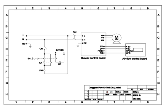
6.2 Electrical drawings
6.2.1 PA-400TS-LD-IQ /PA-500TS-LD-IQ/PA-700TS-LD -IQ/PA-1500TS-LD -IQ:
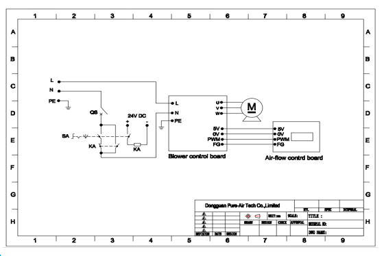
6.2.2 PA-2000TS-LD -IQ/PA-3000TS-LD -IQ:
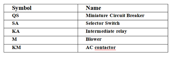
6.3 Electrical components list
7. Contact
Dongguan Pure-Air Tech Co, Ltd
Address: Building 27, HuaKe DingCheng Industry Incubation Zone, DaoJiao Town, Dongguan City, China (P.O.:523182)
TEL: +86-769-2286 7970, Fax: +86-769-2233 4949
WEB: www.pure-airtech.com
EMAIL: sales01@pure-airtech.com



 :
:


