1. Safety Instruction
1.1 General Safety Regulation
Do not attempt to operate until you have read thoroughly and understand completely all instructions, rules, etc. contained in this manual. Failure to comply can result in accidents involving fire, electric shock, or serious personal injury. Keep owners manual and review frequently for continuous safe operation.
1.2Important safety notes
Concerning symbols used on the extraction unit and referred to within this manual.
Danger
Refers to an immediately impending danger. If the danger is not avoided, it could result in death or severe (crippling) injury. Please consult the manual when this symbol is displayed.
Warning
Refers to a possibly dangerous situation. If not avoided it could result in death or severe injury. Please consult the manual when this symbol is displayed.
Caution
Refers to a possibly harmful situation. If not avoided, damage could be caused to the product or something in its environment.
Important (Refer to manual)
Refers to handling tip and other particularly useful information. This does not signify a dangerous or harmful situation. Refer to manual when this symbol is displayed.
Electrical Safety
The system has been designed to meet the safety requirements of the Low Voltage Directive 2006/95/EC.
Other safety caution
Warning
When working with the pump/motor housing open, Live 230/115 volt mains components are accessible. Ensure that the rules and regulations for work on live components are always observed.
Important
To reduce the risk of fire, electric shock or injury:
1.Always isolate the system from the mains power supply before removing the motor access panel.
2.Use only as described in this manual.
3.Connect the system to a properly grounded outlet.
Dangers to eyes, breathing and skin
Once used, the filters within the system may contain a mixture of particulates, some of which may be sub-micron size. When the used filters are moved it may agitate some of this particulate, which could get into the breathing zone and eyes of the operative. Additionally, depending on the materials being lasered, the particulate may be an irritant to the skin.
This unit should not be used on processes with sparks of flammable materials or with explosive dusts and gases, without implementation of additional precautions.
Caution: When changing used filters always wear a mask, safety shoes, goggles and gloves.
Carbon selection
Please note that the media within the gas filter fitted in the system is capable of adsorbing a wide range of organic compounds. However, it is the responsibility of the user to ensure it is suitable for the particular application it is being used on.
1.3 Safety Labels
The following listing details labels used on our fume extraction unit.

Location: Front face of both filters.
Meaning: Goggles, Gloves and Masks should be worn while handling used filters.
Do Not Touch Label
Location: Under the blower air inlet.
Meaning: Do not touchthe holes adjacent to the label.
Electrical Danger
Location: Rear upper & lower access Panels and internal motor access panel.
Meaning: Removal of panels with this label attached will allow access to potentially live components.
Warning Label
Location: Top left front door panel.
Meaning: Power should be isolated before the panel with this label attached is opened/ removed.
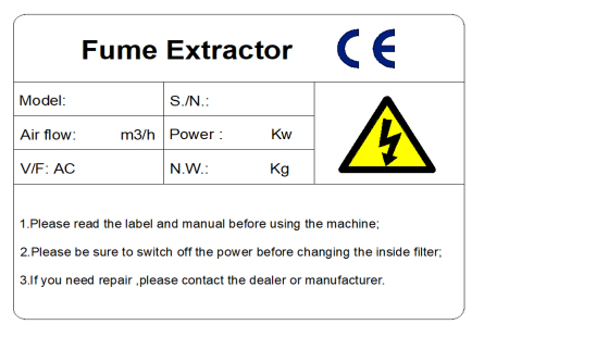
Location: Top right on the right hand side panel.
Meaning: This label contains a variety of information about the extraction unit, including.
A. Machine model;
B. machine factory number;
C. Working voltage and frequency;
D. rated power;
E. Machine weight;
F. company name, address and contact number;
G. Related Marks / Logos
Please note: If the equipment is used in a manner not specified by the manufacturer, the protection provided by the equipment may be affected or equipment components may be damaged beyond repair.
Fire Risk Warning:
In the very rare event that a burning ember or spark is drawn into the fume extraction unit, it may be possible that the filters will ignite.
Whilst any resultant fire would typically be retained within the fume extraction unit, the damage to the extractor would be significant.
It is therefore essential to minimise this risk by undertaking an appropriate assessment to determine:
A). Whether additional fire protection equipment should be installed.
B). Appropriate maintenance procedures to prevent the risk of build-up of debris which could potentially combust.
2. Equipment related parameters
2.1 Equipment functions
(1) .Working principle:
Due to the gravity of the fan, the smoke is sucked into the air inlet of the equipment through the suction hose. There is a front dust box at the air inlet, and a blocking plate is built in.
Sparks and large particles of dust are blocked and dropped into the front dust box. The fine smoke enters the sedimentation chamber. Using gravity and upward airflow, part of the smoke falls to the dust collection drawer inside the machine. The remaining fine smoke is captured by the filter element on the outer surface. After the separation and purification of the high-efficiency filter cartridge, the clean gas passes the fan, and then is discharged at the air outlet.
(2). Features and advantages:
A. Special structure design, small body size, low running noise and movable;
B. Adopting special aluminum alloy impeller and three-phase motor, perfect combination of negative pressure and flow. And stable operation and low failure rate;
C. Set the main power switch. The electronic control components adopt thermal overload protection, phase loss and phase sequence protection, high safety, and can realize remote control.
D. Equipped with high-efficiency Toray polyester fiber coated filter cartridges, the dust and dust filtering efficiency is up to 99.7% @ 0.3 microns (self-tested by us);
E. A fire arrester is installed at the air inlet to prevent sparks from directly contacting the filter cartridge and damaging the filter cartridge;
F. Unique automatic rotary pulse backflushing device, good dust removal effect;
G. Special air duct and noise reduction design, reduce the noise of the air outlet of the machine;
H. Stainless steel case can be customized according to customer requirements.
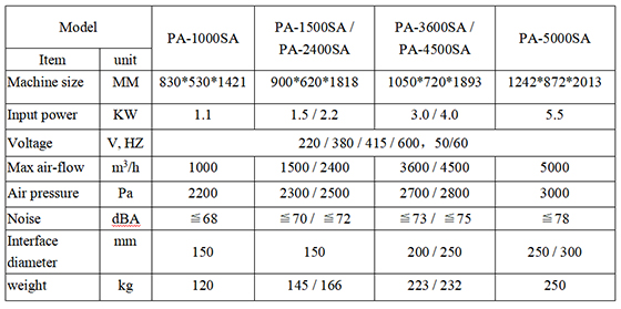
2.3Filter elements Data

2.4 Appearance parts drawing
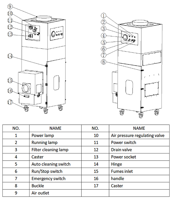
3. Installation
3.1 Installation instructions
Before installation, the internal and external shipping packaging should be removed and the machine inspected for damage. Remove all the packaging before connecting the device to a power source.
Please read all instructions in this manual before using this fume extractor.
(1). Move the device to the location where you want to install it, and then remove the packaging. The device should be installed in a well-ventilated area.
(2). Open the top cover, check and ensure that the internal filter is smoothly placed in the limit interval, and check the top cover and the filter are sealed.
Attention:
A. Due to the weight of the fume extractor, proper handling methods and proper safety precautions should be followed.
B. Make sure that there is a space of 500 mm on the side of the air outlet of the fume extractor to ensure that there is sufficient air flow out.
(3). Lock the brake of the machine's casters to prevent the machine from sliding. (Some models do not have casters installed as standard.)

Attention:
A. Do not block or cover the air inlet on the device, as this will severely restrict airflow and may cause damage to the device.
B. Under no circumstances should the exhaust vent be covered as this will restrict airflow and cause overheating
3.2Installation
(1). Installation process:
Planning location line →Moving the device→Connecting power line→Test
(2). Machine assembly sequence: first assemble the host, then assemble the interface, power and signal cables.
Note: Confirm the distance and the flatness of the ground before assembly.。
3.3Power requirements
A. Insufficient power supply voltage may affect the power output function of the motor.
B. It is important to connect the unit to the correct voltage in the factory power source and use a separate power source.
C. Power requirements:
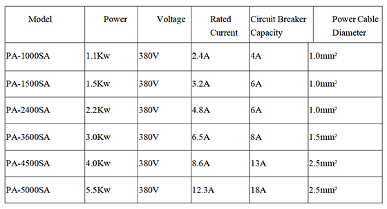
3.4 Check connection of power lines
Must check whether the power cord is connected to the correct connection point.
4. Operation
4.1 Control Panel
(1). Power indicator: plug in the power, turn the main switch on the power socket, the power indicator turns green;
(2). Run / stop switch: machine start stop button;
(3). Running indicator: the machine starts running, the indicator turns green; the machine stops, the indicator goes off;
(4). Automatic cleaning switch: Automatically clean the filter cartridge button with compressed air;
(5). Dust removal indicator: Automatic dust removal starts, the indicator turns green; automatic dust removal stops, the indicator goes out;
(6). Emergency stop switch: Emergency stop is required,Press the emergency stop button immediately to cut off the power supply of the machine. After the problem is solved, emergency stop switch turn right to resume.
4.2Operating procedures
(1). Power connection: Before connecting the power, you must confirm that the voltage and frequency meet the rated standards of the equipment.
(2). Air pipe connection: The air pipe and equipment connection need to be properly sealed to avoid the pipeline from collapsing and affecting the air flow.
(3). Compressed air connection: The top of the filter cartridge in the PA-5000SA purifier has a sealed cylinder. The cylinder must be lifted before it can run.
(4). Plug in the power socket, turn the red "power switch" to the "ON" position clockwise, and the green "power indicator" lights up.
(5). Press the green "Run/Stop Switch" button to start the machine. Press again to stop the machine.
(6). The machine of this system is equipped with an offline automatic blowing system, and the filter can be cleaned by pulse blowing when the purifier is running. When the offline automatic cleaning system works, the purifier needs to be connected to compressed air. The factory default setting is that the filter cartridge will automatically perform pulse blowing one by one every one hour when the machine runs for about 10-15 minutes. There is no need to stop during the spraying process, and it does not affect the customer's use of the purifier. Customers can also adjust the interval and duration of pulse injection according to the actual situation.
(7). Do not cut off the main power after the machine is shut down every day or when the pointer of the pressure gauge on the control panel reaches about 0.7-0.8KPa. Ensure that the air inlet of the air pressure regulating valve on the machine is connected to the air compressor outlet pipe. The air pressure regulating valve shows that the air pressure is not lower than 0.5MPa.
Press the green "Automatic Ash Cleaning Switch" button, the "Green Ash Cleaning Indicator" lights up, the automatic pulse backflushing dust cleaning system is started, and high pressure backflushing is performed from inside the filter element. Blow the dust deposited on the surface of the filter element to the dust collection drawer to make the surface of the filter element clean. The automatic dust removal system runs for about 10-15 minutes or when the pointer of the differential pressure gauge returns to about 0.5KPa, press the "Automatic dust removal switch" button again, the indicator light goes out, and the blowback dust removal stops.
(8). When the pointer of the differential pressure gauge on the control panel reaches about 1.2-1.5KPa, manual cleaning can be used for deep cleaning to extend the service life of the filter element. Open the door in the middle of the case, use the air gun to blow the inside of the filter cartridge directly, or take out the filter cartridge, and use the air gun to deeply clean the filter cartridge.
5. Maintenance
5.1Equipment cleaning
After the equipment has been used for a period of time, the stainless steel unit should be cleaned with a special stainless steel cleaner in accordance with the manufacturer's instructions. Powder-coated machines can be cleaned with a damp cloth and non-abrasive cleaners. Do not use abrasive cleaning products, which can damage the surface.
The dust inlet and air outlet should be cleaned about once a month to prevent dust from accumulating and causing the device to overheat.
5.2 Cleaning the filter element
(1). Automatic filter cleaning offline:
When the offline automatic cleaning system works, the purifier needs to be connected to compressed air. The factory default setting is that the filter cartridge will automatically perform pulse blowing one by one every one hour when the machine runs for about 10-15 minutes. There is no need to stop during the spraying process, and it does not affect the customer's use of the purifier. Customers can also adjust the interval and duration of pulse injection according to the actual situation.
(2). Daily automatic cleaning filter:
Do not cut off the main power after the machine is shut down every day or when the pointer of the pressure gauge on the control panel reaches about 0.7-0.8KPa. Ensure that the air inlet of the air pressure regulating valve on the machine is connected to the air compressor outlet pipe. The air pressure regulating valve shows that the air pressure is not lower than 0.5MPa.
Press the green "Automatic Ash Cleaning Switch" button, the "Green Ash Cleaning Indicator" lights up, the automatic pulse backflushing dust cleaning system is started, and high pressure backflushing is performed from inside the filter element. Blow the dust deposited on the surface of the filter element to the dust collection drawer to make the surface of the filter element clean. The automatic dust removal system runs for about 10-15 minutes or when the pointer of the differential pressure gauge returns to about 0.5KPa, press the "Automatic dust removal switch" button again, the indicator light goes out, and the blowback dust removal stops.
(3).Manual deep cleaning filter:
When the pointer of the differential pressure gauge on the control panel reaches about 1.2-1.5KPa, manual cleaning can be used for deep cleaning to extend the service life of the filter element. Open the door in the middle of the case, use the air gun to blow the inside of the filter cartridge directly, or take out the filter cartridge, and use the air gun to deeply clean the filter cartridge.
5.3 Replacing the filter element
The filter cartridge of this series of machines can be reused after cleaning with compressed air. After the filter cartridge fails (the air volume becomes small even after manual cleaning or the air volume is still small after the filter element is cleaned), please replace with a new filter cartridge. The replacement method is as follows:
(1). Wear gloves and protective mask, and open the lock of the front door of the filter cartridge layer of the chassis;
(2). Rotate and remove the filter cartridge counterclockwise, put it in a plastic bag and seal it well;
(3). Align the new filter cartridge with the filter cartridge chuck, rotate the filter cartridge clockwise to lock the filter cartridge; close the front door, and lock the case.
5.4Trouble shooting guide
(1). Fault indication
If there is a problem with the purifier, read this section of the manual before contacting the helpline.
(2). Motor failure
If the purifier has a motor-related fault, it will stop running.
(3). Internal power supply
The internal power supply is equipped with accessories such as AC contactors, phase sequence protectors, thermal overload relays, transformers, etc., which should be checked to prove that it is usable, if not, it should be checked or replaced.
(4). Dust removal failure
A pulse controller is installed inside the machine. If there is a cleaning failure, please check whether the pulse controller can supply power or whether it is operating normally. If there is no power, check the wiring to see if the terminals are loose. If the pulse controller is not working properly, please restart to see if it is normal. If you still have problems, please contact the after-sales personnel to assist in handling.
6. Electricity
6.1 Electrical control system safety rules
(1). Only personnel with appropriate training and sufficient knowledge and skills can perform all electrical troubleshooting and repairs.
(2). Do not change or bypass the protective interlock.
(3). Read and follow all warning labels before you start.
(4). Make sure the power is off and the main switch is off when troubleshooting.
(5). Take extra precautions to prevent accidental grounding when used in humid places.
(6). Before powering up the equipment, there must be no doubt that all persons operating are clear.
(7). Do not open the electrical control panel unless the electrical equipment must be inspected.
(8). Circuits must not be changed unless authorized by the manufacturer.
(9). When replacing electrical components, make sure they meet the manufacturer's specifications, including the correct numbering.
(10). Do not wear metal frame glasses, metal necklaces or chains when working on any electrical equipment. Even when operating electrical equipment wear any ring, watch or bracelet.
6.2 Electrical drawings
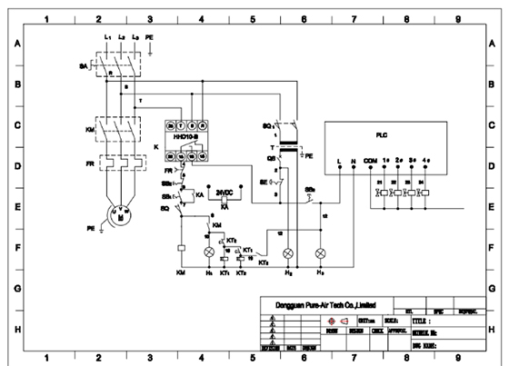
6.3Electrical components list
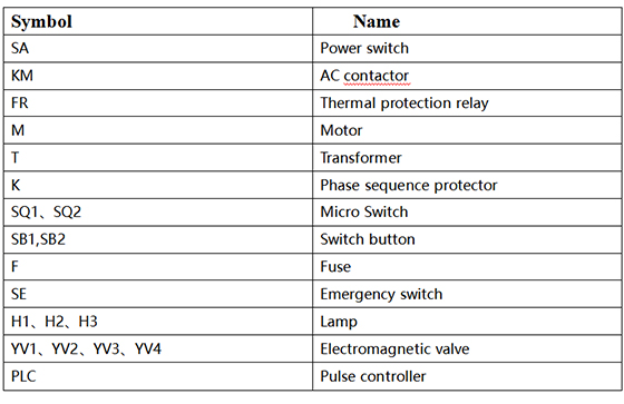
7. Contact
Dongguan Pure-Air Tech Co, Ltd
Address: Building 27, HuaKeDingCheng Industry Incubation Zone, DaoJiao Town, Dongguan City, China(P.O.:523182)
TEL: +86-769-2286 7970, Fax: +86-769-2233 4949
WEB: www.pure-airtech.com
EMAIL: sales01@pure-airtech.com

